Garage Openers - PFC CONTROLS | Miami, Gate Operators, Sliding Gate, Swing Gate, Intercoms, Turnstiles, Bollards, Barrier gate

MENU
Go to content

7 Best Automated Tank Filling Solutions for 2026

Choosing the right Automated Tank Filling Solution can improve accuracy, reduce spills, and give operators clearer control over each batch. In 2026, buyers will compare more than filling speed. They will also assess flow-meter accuracy, valve response, cleanability, alarm handling, and integration with existing controls. A useful system should handle everyday production, not just perform well in a product demo. Small details matter.

Quality-management expert W. Edwards Deming famously said, “A bad system will beat a good person every time.” His observation applies to tank filling: dependable results come from sound equipment, clear procedures, and reliable feedback—not operator vigilance alone. The seven solutions in this guide are considered through practical criteria, including liquid compatibility, target-volume control, installation demands, and service support. A food plant filling viscous syrup, for example, may need different pumps and cleaning provisions than a facility handling thin process water. There is no universal winner. Some systems may offer impressive automation but require more integration work than a smaller operation can justify. That trade-off is easy to overlook. This guide highlights the strengths and limitations of leading approaches, helping readers shortlist options and ask vendors specific questions before investing.
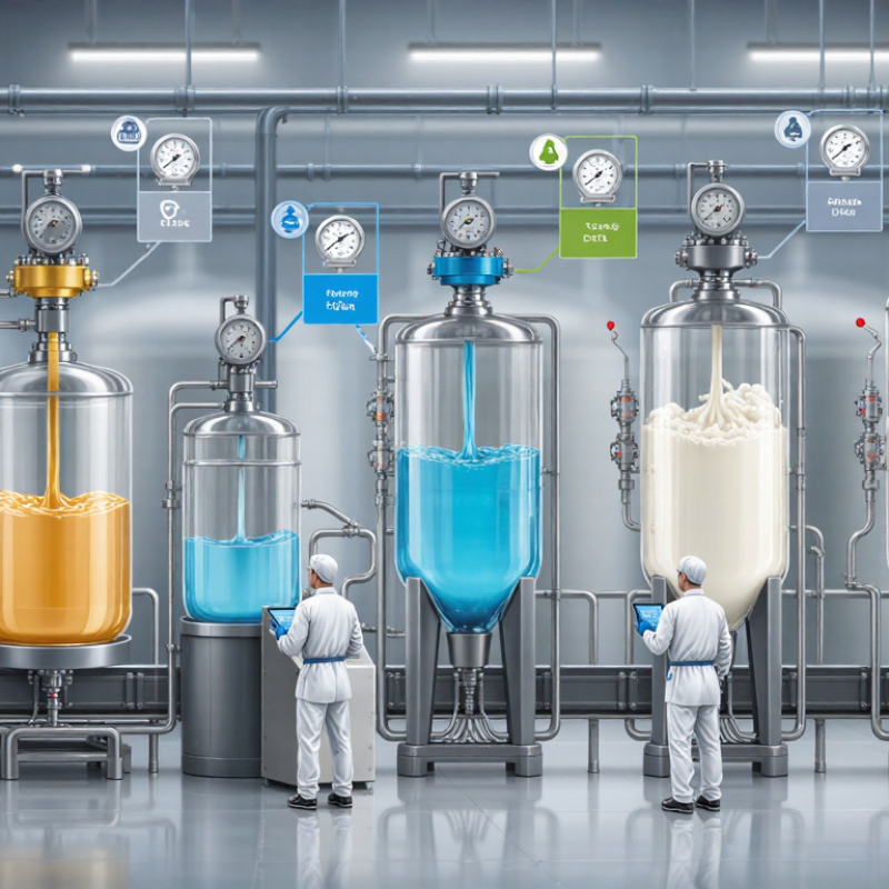
7 Best Automated Tank Filling Solutions for 2026

Core Technologies Behind Automated Tank Filling Systems

Automated tank filling systems combine measurement, control, and fluid-handling components to deliver repeatable batches. A flow meter tracks volume as liquid moves through a pipe, while a level sensor monitors the tank itself. These signals are not interchangeable: foam, turbulence, and tank geometry can distort level readings. Small details matter.

A programmable controller compares live readings with a target and adjusts pumps or valves near the setpoint. For example, a system may fill quickly at first, then reduce flow before the final liters to limit overshoot. Viscous liquids may need slower flow and appropriately sized lines, which can improve consistency but lengthen each cycle. A high-level cutoff adds protection if the primary measurement drifts. It is not a substitute for maintenance.

Reliable installations need calibration, leak checks, and test runs with the actual liquid and operating temperature. Operators should verify alarms, emergency stops, and restart behavior after a power loss. That last check is often overlooked. Even a clean display can create false confidence. Sensors can foul, and valves can stick; accuracy depends on regular inspection and realistic testing. The right setup also depends on cleaning needs, tank shape, and the variation a process can tolerate.

Key Components and How They Work Together

An automated tank-filling system works best when its components are matched to the liquid and container. Product moves from a supply tank through a pump and controlled valve toward the filling nozzle. The pump sets the flow rate, while the valve starts or stops delivery. A flow meter measures volume; load cells beneath the receiving tank can verify weight as a separate check.

Small details matter. Nozzle height and shutoff timing affect splashing, drips, and fill consistency.

A programmable controller combines sensor readings with the target fill setting. When the measured amount reaches the setpoint, it closes the valve and may slow the pump near the end. Level sensors protect the supply tank from running dry, while an emergency stop and guarding support safe operation. An operator interface displays alarms and lets trained staff adjust recipes or inspect cycle data.

Still, a neat sequence on screen can behave differently with a cold, viscous liquid. That gap matters.

Testing at real operating temperatures, then checking calibration and actual filled weights, can catch problems a simulation may miss. Calibration can drift.

Criteria for Comparing Automated Filling Solutions

Comparing automated tank filling solutions starts with the product, not the advertised speed. Viscosity, foaming, temperature, and particles can change how a tank fills. A thin liquid may flow steadily, while a syrup can cling to the line and affect cutoff timing. Test with the actual fluid whenever possible. Bench results matter.

Check fill accuracy at the smallest and largest target volumes, not just one convenient setting. Review how the system handles start-up, pauses, and end-of-batch drips. A fast cycle is not useful if operators must correct frequent underfills. Ask for repeatability data and clarify how it was measured. Numbers need context.

Compare tank-level sensing, valve response, cleaning compatibility, and changeover time. Check wetted materials, access to seals, and whether calibration can be verified without lengthy downtime. Controls should display alarms clearly and record useful batch data. Consider installation limits, operator training, spare parts, and service response. These details often shape real operating costs. Still, no scorecard captures every awkward corner case; a trial run may reveal a problem the specification sheet misses.

Seven Automated Tank Filling Solutions for 2026

Automated tank filling in 2026 covers more than a pump that stops at a preset level. A level-sensor system is a practical choice for steady liquids: sensors detect the target height and signal a valve or pump to shut off. A flow-meter system measures the volume passing through a pipe, making repeatable batches easier to manage. For higher accuracy, a load-cell system weighs the tank as it fills. It can be useful when liquid density changes, though tank supports and vibration can affect readings. Small details matter.

A PLC-controlled filling system coordinates pumps, valves, alarms, and operator settings from one panel. It can run consistent recipes, but setup still needs careful testing. A gravimetric dosing system weighs each ingredient into a tank, helping facilities control multi-part blends. A mobile filling skid brings a compact pump, meter, and controls to different tanks. This can save floor space, but hoses and connections need regular inspection. It is not magic.

Remote monitoring is a seventh option. Networked sensors can report levels, flow rates, and faults to a dashboard, helping staff spot unusual readings before a tank overflows. Data is only useful when sensors are calibrated and alerts reach someone who can respond. The right configuration depends on fluid behavior, required fill tolerance, cleaning needs, and the cost of downtime. In real installations, one sensor may behave oddly after a temperature change, so commissioning should include realistic operating conditions.

Choosing and Implementing the Right System

Choosing a tank-filling system starts with the liquid, not the equipment catalog. Record its viscosity, temperature, foaming behavior, and required batch tolerance. Then check tank geometry, inlet position, and the available utilities. A level sensor may work well with a calm liquid, while turbulent or foaming products can produce unreliable readings. Consider a flow meter or independent high-level cutoff where an overflow would be costly. Small details matter.

The 2024 Deloitte Smart Manufacturing Survey found that 86% of surveyed manufacturing executives expect smart manufacturing solutions to drive competitiveness within five years. That is a broad manufacturing outlook, not a tank-filling performance guarantee. Use it as context, not proof that a more connected system will suit your plant. During implementation, test the chosen controls with real product and realistic fill rates. Verify shutoff behavior, alarm response, and restart procedures with operators present. Keep manual isolation accessible. It may seem obvious, but it is often overlooked.

Plan for cleaning, calibration, and sensor replacement before installation. A system that fills accurately but takes hours to inspect can create a different bottleneck. Document acceptable fill variation and define who responds when readings disagree. Pilot one line if production allows; awkward issues often appear only during shift changes. No specification sheet captures every habit on the floor.

7 Best Automated Tank Filling Solutions for 2026 - Choosing and Implementing the Right System
Automated Filling Solution Best Suited For Indicative Batch Accuracy Key Advantages Main Limitations Implementation Priorities
Load-cell gravimetric filling Ingredient batching, high-value liquids, and applications where the filled mass matters more than volume. Often planned around ±0.1–0.5% of the target batch under suitable conditions; verify with the actual tank, load cells, and process. Measures the tank’s weight directly; does not rely on liquid density or flow-meter calibration. Vibration, pipe forces, tank contact, and changing load distribution can affect readings. Flexible connections and stable supports are important. Use correctly sized load cells, isolate the vessel from rigid pipework, and validate zero and span with traceable test weights or a suitable calibration procedure.
Coriolis mass-flow metering Precise batch transfer of many liquids, including products whose density may vary. Meter specifications can be around ±0.1–0.2% of reading in suitable conditions; installed batch performance is application-dependent. Measures mass directly and can also provide density and temperature data; generally does not require straight pipe runs for flow conditioning. Higher initial cost; sizing, pressure drop, entrained gas, and very low flow rates can affect performance. Size for the normal and minimum flow rates, remove air where practical, and use a fast-close valve with a tested cutoff or drip-compensation setting.
Electromagnetic flow metering Conductive liquids such as water, many aqueous solutions, and compatible slurries. Many installations can target roughly ±0.2–0.5% of reading; actual batch accuracy depends on meter sizing and installation. No moving parts in the flow stream; suitable for many conductive, dirty, or particle-bearing liquids. Cannot meter non-conductive liquids such as many oils and solvents; the pipe must remain full for reliable measurement. Confirm the liquid’s conductivity and liner compatibility, keep the meter full, provide grounding as specified, and avoid unsuitable installation locations.
Positive-displacement flow metering Viscous liquids, oils, syrups, and other fluids where a repeatable volume measurement is needed. Often specified in the approximate ±0.2–0.5% range for suitable fluids and operating conditions; confirm the selected meter’s calibration data. Measures discrete volumes and can perform well with viscous products; many designs work at relatively low flow rates. Moving parts can wear; solids, abrasive products, and inadequate lubrication may reduce service life or accuracy. Check viscosity and particle content, install filtration only where product requirements allow, and provide maintenance access and calibration checks.
Turbine flow metering Clean, relatively low-viscosity liquids with stable flow and a suitable operating range. Commonly planned around ±0.5–1% of reading in appropriate conditions; performance can deteriorate outside the calibrated range. Compact and responsive, with a pulse output that can integrate readily with batch controllers. Moving components are sensitive to contamination and wear; viscosity changes and swirl can affect readings. Use clean fluid, follow straight-run and flow-conditioning guidance, select the correct meter range, and monitor pulse output for faults.
Ultrasonic flow metering Clean liquids in full pipes when avoiding wetted meter parts is important; clamp-on units can be installed without cutting the pipe. Clamp-on performance is installation-dependent; a planning range of roughly ±1–3% may be more realistic than precision batch-meter assumptions. Non-invasive clamp-on installation is possible, avoiding direct contact with the product and simplifying retrofit work. Pipe material, wall condition, air bubbles, deposits, and flow profile can affect signal quality and measurement accuracy. Confirm pipe and liquid compatibility, enter pipe dimensions accurately, locate the sensor on a suitable full pipe, and validate results against a reference.
Level-based filling with independent overfill protection Bulk tank filling where the required endpoint is a liquid level rather than a precisely measured batch quantity. Volume accuracy depends on tank geometry, sensor accuracy, liquid surface conditions, and calibration; it is generally less suitable for small, high-precision batches. Radar or ultrasonic level instruments can provide continuous level data; a separate high-high level switch can add an independent shutdown layer. Foam, turbulence, obstructions, tank geometry, and changing liquid properties can complicate level-to-volume conversion. Calibrate the tank’s level-to-volume table, position the sensor for a clear measurement path, and test independent high-level alarms and shutoff functions.

Selection note: Accuracy figures are indicative engineering planning ranges, not guaranteed results or directly comparable meter specifications. Confirm performance with the supplier for the actual liquid, batch size, flow range, piping, temperature, and installation. For hazardous or regulated processes, complete the required safety review and use appropriately rated equipment.

PFC CONTROLS
1638 NW 108TH AVE. MIAMI, FL 33172
Sales: (305) 593-0227
Tech: (305) 546-3965

Copyright, All rights reserved
Back to content